CS23 Final Project Description
 K. Ganchev
 S. Finney
 F. He
Introduction
Modern microprocessors employ a high level of parallel computing in the form of
superscalar design as well as extensive pipelinig. However, these still
typically implement a purely sequential instruction set, ususally far more
complex than the internal instruction set of the internal processor itself. To
bridge the gap between the sequential instruction set and the highly parallel
machine, most modern microprocessors employ a large pre-processing unit that
translates the byte-code in real time into a risc instruction set that is then
executed in parallel. This allows a great increase in performance, but the
overhead computation has to be performed both in real time and many times over
(each time a section of code is executed).

Intel's IA64 instruction set is explicitly parallel to transfer this work to
the compiler so that it is executed only once with a far weaker time constraint
to allow better code optimization. The IA64 instruction set is an ambitious
project that uses several other modern ideas to improve perfomance. It may be
the case that it is even too mabitious because years after defining the
instruction set Intel has still not implemented it in a processor.

For this final project we defined a simpler EPIC RISC instruction set, and
implemented it in VHDL. Since using an EPIC instruction set transfers much of
the work to the compiler, we also defined an assembly language that does not
concern itself with concurrency and wrote an assembler and optimizer to
translate a program written in the assembly language into an equivalent
explicitly parallel program. The processor that we implemented has two ALUs,
but the instruction set is designed in such a way that a program can be run on
a processor with an arbitrarily large number of ALUs and use all the ALUs
without requiring recompilation.
Instruction Set
In order to prove the concept of an explicitly parallel instruction set,
without having to implement a very complicated set of poerations and special
cases, we defined defined the following simple 32 bit instruction set.

Bit Assignments:

x xxx xxxx xxxx xxxx xxxxxxxxxxxxxxxx
|  |   |    |    |      |
|  |   |    |    |      +- data field (16 bits)
|  |   |    |    +-destination
|  |   |    +- source B
|  |   +- source A
|  +- opCode
+- set bit

  ALU Ops (in hex)

  0 - Add
  1 - OR
  2 - AND
  3 - XOR
  4 - 1's complement of A
  5 - Shift A right, pad with rightmost of B
  6 - Shift A left, leftmost bit of B
  7 - JMP negative - jump if A is negative

  Register Codes (in hex)

  0 - reg 0
  1 - reg 1
  2 - reg 2
  3 - reg 3
  4 - reg 4
  5 - reg 5
  6 - reg 6
  7 - reg 7
  8 - reg 8
  9 - reg 9
  A - reg 10
  B - reg 11
  C - reg 12
  D - 0
  E - 1
  F - data bits of instruction

The source, operation code and destination bits are fairly self-explanatory, so
I will not describe them here. The 16 data bits at the end of the instruction
can be used as a source register, and also specify the address to jump to if
the instruction is a jump. What makes this instruction set explicitly parallel
is the first bit of each instruction called the set bit.

The Set Bit

The instructions that make up a program are divided into arbitrarily large sets
such that all the instructions of a set can be executed in parallel. In order
to deliminate different sets, a set bit is added to each instruction and any
two consecutive instructions that have the same bit are in the same set. The
example below might make it clearer:

0xxxxx...  \
0xxxxx...   } set 1
0xxxxx...  /

1xxxxx...  \
1xxxxx...   > set 2

0xxxxx...   } set 3

1xxxxx...  \
1xxxxx...   \
1xxxxx...    >set 4
1xxxxx...   /

The processor loads as many instructions as it has ALUs but only executes as
many as are in the same set as the instruction being executed by the first ALU.
In this way arbitrarily many ALUs can execute code in parallel with sets
defined by a single bit.
The Assembly Language
We defined the following assemblu language and built an assembler to translate
it into our instruction set:

Any characters in a line after a ';' (no quotes) are ignored - this is
to allow commenting.

The format of the instructions are

[OP CODE] [SOURCE A] [SOURCE B] [DESTINATION] [optional DATA]

The op code is a string from the following table:

  "ADD"	Add source A and source B and save the result to the destination
  "OR"	Store the bit-wise or of source A and source B to the destination
  "AND" Store the bit-wise and of source A and source B to the destination
  "XOR" Store the bit-wise xor of source A and source B to the destination
  "NOT" Store the bit-wise not of source A to the destination
  "SR"  Store source A shifted right 1 position padded with the right
	most bit of B
  "SL"	Store source A shifted left 1 position padded with the left
	most bit of B
  "JN"	If source A is negative jump to the adress specified by the DATA field

The source and destinations are from the set:
  "R00"	general purpose register 0
  "R01"	general purpose register 1
  "R02"	general purpose register 2
  "R03"	general purpose register 3
  "R04"	general purpose register 4
  "R05"	general purpose register 5
  "R06"	general purpose register 6
  "R07"	general purpose register 7
  "R08"	general purpose register 8
  "R09"	general purpose register 9
  "R10"	general purpose register 10
  "R11"	general purpose register 11
  "R12"	general purpose register 12
  "ZRO" all bits zero
  "ONE" all bits zero except the least significant bit
  "DAT" the data bits of the instruction

Note that if "ZRO", "ONE" or "DAT" is specified as the destination register,
then the output value is ignored.

The Assembler:

The assembler is a very simple program. It parses each line of the source code
and applies each token on that line to the final instruction (stored as a 32
bit integer). When it reaches the end of the line, or a ";" it moves on to the
next line. If any token is missing or has an invalid value, it errors out,
printing the line that it could not parse. The only token that is optional is
the data field, which has a default value of 0. The assembler writes the
bytecode for the program into a binary file (4 bytes per instruction).

We wrote a program to read these bytes and print the output as a sequence of 0s
and 1s so that humans can read the bytecode.
The Optimizer
The process of optimization has been kept implicitly separate from the
process of parsing and assembling the code for the computer, which adds
incredble flexibility, portability, and readability to the project.

The output from the assembler is completely functional as stand-alone
code in its own right, only it is explicitly serial.  The group set
bit (0x80000000) alternates 1/0 every other instruction, implying that
each operation is dependant on each previous operation, and thus must
be executed in order one at a time.

The optimizer then takes this code and rearranges instructions and changes
the set bits so that the code can be executed in parallel by any number
of processors/ALU's configured to run our instruction set in parallel.

What follows is a shortened version of the algorythm used to optimize
the compiled code (For a throrough explanation of the algorythm,
please read through optimizer.c and optimizer.h--both of which of are
heavily commented and cleanly coded).

Needed data structures:
'a' queue of a #defined size of the first N unoptimized instructions in
    the file
'b' queue of the optimized code
'c' two tables for holding read and write dependency information
'd' queue of jump destinations

The Alg. in a nutshell:
1] read N lines into 'a'
2] from a[0] to a[N],
	--if a[i] is a location in 'd', it starts a new set group
	--if dependencies aren't already in 'c', add a[i] to
	  'b', and remove it from 'a'.  regardless, add a[i]'s dependencies
	  to 'c'
	--if a[i] is a jump operation, it is the last operation in a setbit
3] read in however many members were removed in step 2.
CPU Organization
Overview:
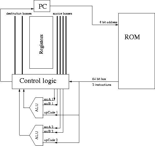
The CPU has 13 16-bit general purpose registers, 1 8-bit program
counter (PC) (this can be easily expanded to 16 bits), 2 ALUs. The ROM
stores two 32 bit instructions (of a 64 bit total) at one address. The
instructions are interleaved (explained later) to facilitate parallel
processing.
 VHDL Implementation:
The entire project consists of 3 files:
epic_cpu.vhd includes the registers and control logic
alu.vhd defines the ALU
maxgram.mif is the ROM -- it stores the program to be executed.
The CPU is implemented as state machine with four states, representing
the four states of complete CPU cycle.
The CPU creates two instanciations of the ALU. There is a wide bus
connecting the ROM to the CPU.
Fetch/Execute Cycles:
A complete CPU cycle consists of four stages: fetch, decode, execute,
and store.
On the rising edge of the fetch clock cycle, CPU applies
the PC to ROM, and fetchs two instructions from ROM.
On the rising edge of the decode clock cycle, the control logic in CPU
dispatches operands and op-codes to the two ALU's. Note that the two
instructions and operands are always passed to the ALU's regardless of
their dependency.
Because in our implementation, the ALU's are defined in a separate
file, and port mapped to the CPU, the execute cycle is simply
a wait cycle, while the ALU's put the results on the buses.
On the store cycle, the CPU always commits the first
instruction. Whether the second instruction is committed is determined
by comparing the set bits of the two instructions (in fact an XOR
operation). If the set bits are the same, the second instruction is
also committed. If not, the result is not used. Note that, even if one
or both of the instructions is a jump, they are still committed in
this manner.
ROM:
The ROM stores 4-word-chunks of instructions bundles (one word = 32
bits). Each bundle has two consecutive instructions. As we would like
to jump to any instruction, we need a way to address every
instructions. We achieve this by "interleaving" the instructions
(it's not the best word to describe it, but the term stuck among the
group memebers). Suppose the original binary code looks like:
addr instruction
0 I1
1 I2
2 I3
... .....
After interleaving, the code (ready to be executed by the CPU) looks
like:
addr instruction bundle
0 I1 & I2
1 I2 & I3
2 I3 & I4
... .....
This increase the code size by a factor of 2, but each instruction can
be addressed individually. The utility (interleave.c) converts binary
code to interleaved/human-readable code. Here's a sample output:
-- Assembly Code:
bay[~/cs23/lab5]% cat tests/test1.fgh
; this is the simplest test.. we add independant stuff and display it
ADD ZRO ZRO R01
ADD ONE ONE R00
-- Binary Code (bincat converts binary to human-readable):
bay[~/cs23/lab5]% ./bincat tests/test1.out
00001101110100010000000000000000
10001110111000000000000000000000
-- Interleaving:
bay[~/cs23/lab5]% ./interleave tests/test1.out
00000000 : 0000110111010001000000000000000010001110111000000000000000000000
00000001 : 1000111011100000000000000000000000000000000000000000000000000000
Notice that the second instruction at addresss_0 is the same as the
first instruction at address_1.
Interleaving is far from being the most efficient way to make each
instruction addressable. We had to resolve to this because in VHDL ROM
returns only the value stored at one address at a time (or we didn't
know of a way to get around it in VHDL). In reality, memory can be
easily implemented to return values from two consecutive memory
addresses.
VHDL Implementation:
The entire project consists of 3 files:
epic_cpu.vhd includes the registers and control logic
alu.vhd defines the ALU
maxgram.mif is the ROM -- it stores the program to be executed.
The CPU is implemented as state machine with four states, representing
the four states of complete CPU cycle.
The CPU creates two instanciations of the ALU. There is a wide bus
connecting the ROM to the CPU.
Fetch/Execute Cycles:
A complete CPU cycle consists of four stages: fetch, decode, execute,
and store.
On the rising edge of the fetch clock cycle, CPU applies
the PC to ROM, and fetchs two instructions from ROM.
On the rising edge of the decode clock cycle, the control logic in CPU
dispatches operands and op-codes to the two ALU's. Note that the two
instructions and operands are always passed to the ALU's regardless of
their dependency.
Because in our implementation, the ALU's are defined in a separate
file, and port mapped to the CPU, the execute cycle is simply
a wait cycle, while the ALU's put the results on the buses.
On the store cycle, the CPU always commits the first
instruction. Whether the second instruction is committed is determined
by comparing the set bits of the two instructions (in fact an XOR
operation). If the set bits are the same, the second instruction is
also committed. If not, the result is not used. Note that, even if one
or both of the instructions is a jump, they are still committed in
this manner.
ROM:
The ROM stores 4-word-chunks of instructions bundles (one word = 32
bits). Each bundle has two consecutive instructions. As we would like
to jump to any instruction, we need a way to address every
instructions. We achieve this by "interleaving" the instructions
(it's not the best word to describe it, but the term stuck among the
group memebers). Suppose the original binary code looks like:
addr instruction
0 I1
1 I2
2 I3
... .....
After interleaving, the code (ready to be executed by the CPU) looks
like:
addr instruction bundle
0 I1 & I2
1 I2 & I3
2 I3 & I4
... .....
This increase the code size by a factor of 2, but each instruction can
be addressed individually. The utility (interleave.c) converts binary
code to interleaved/human-readable code. Here's a sample output:
-- Assembly Code:
bay[~/cs23/lab5]% cat tests/test1.fgh
; this is the simplest test.. we add independant stuff and display it
ADD ZRO ZRO R01
ADD ONE ONE R00
-- Binary Code (bincat converts binary to human-readable):
bay[~/cs23/lab5]% ./bincat tests/test1.out
00001101110100010000000000000000
10001110111000000000000000000000
-- Interleaving:
bay[~/cs23/lab5]% ./interleave tests/test1.out
00000000 : 0000110111010001000000000000000010001110111000000000000000000000
00000001 : 1000111011100000000000000000000000000000000000000000000000000000
Notice that the second instruction at addresss_0 is the same as the
first instruction at address_1.
Interleaving is far from being the most efficient way to make each
instruction addressable. We had to resolve to this because in VHDL ROM
returns only the value stored at one address at a time (or we didn't
know of a way to get around it in VHDL). In reality, memory can be
easily implemented to return values from two consecutive memory
addresses.
Comparison
Compiled binary code is optimized using the optimizer (optimizer.c) to
take advantage of the parallel architecture. Here's an example of
running a test program before and after optimization:
Human readable code of the program:
ADD ZRO DAT R01 15
ADD ONE DAT R02 15
ADD R01 R02 R00
SL R00 R00 R00
XOR R01 R02 R01
ADD R02 DAT R00 1
This program can be optimized in many ways. One way is to bundle
instruction 1, 2, and 5, 6 together respectively.
Before optimizatoin, the program takes six CPU cycles to complete.
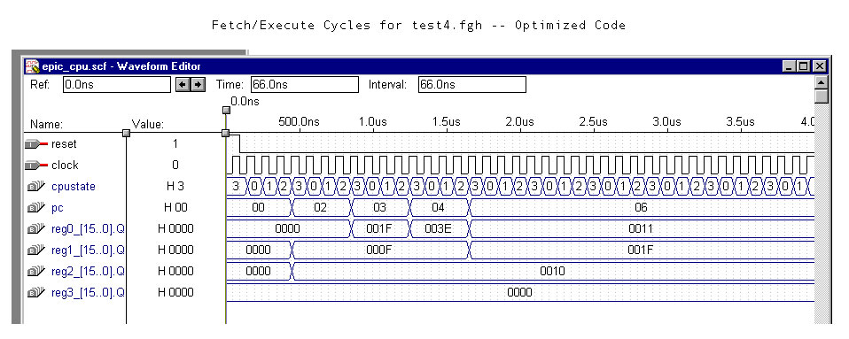
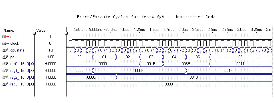 After optimization, the program takes four CPU cycles to complete.
That's a performance improvement of 33%.
After optimization, the program takes four CPU cycles to complete.
That's a performance improvement of 33%.
Improvements
Scaling

We considered whether this would scale to more than two ALUs per processor, and
decided that this should be possible. We came up with the following way of
deciding which instructions can be committed once they have been fetched and we
have access to the set bits:

We have a bus that is one line less wide than we have ALUs. The bus lines float
high, unless they are pulled low by one or more ALUs. Each ALU after the first
compares the set bits of its instruction and the instrction of the previous
ALU. If they are different, then it pulls the bus line corresponding to it and
all ALUs that get instructions after it low. Then each ALU can monitor its bus
line and only commit if its bus line is high (i.e. no one hs pulled it low).
We can use a similar technique (ANDing the bus lines and their inverses) to
determine by how much to increment the program counter.

Flags

We did not implement flags since they would have added a lot of complexity to
the VHDL code, without demonstrating anything novel. Having said that, we also
considered what implementing them would entail. The optimizer would have to
treat each instruction as writing to the flags, but would have to ignore write
after write dependancies. The CPU would then have to write the flags from the
last ALU in the set that commits.

Predicated instructions

It quickly becomes clear that the most complicated and costly (time-wise)
instruction is a jump. This is the case even if we are only jumping a small
amount. We saw that in order to optimize the code correctly we needed to know
which instructions could be jumped to (these had to be the start of a new set),
as well as all the instructions that could cause a jump (these had to be at the
end of a set. Implementing predicated instructions would then yeild a great
improvement in performance over implementing if-then-else statements with
jumps. This would not have been very difficult to implement, but we decided to
concentrate our efforts on getting a working EPIC RISC machine, as well as an
assembler and optimizer for that machine.
Note: Knowing what instructions you can jump to may seem like a fairly heavy
restriction, but if we were implementing a compiler for a high-level language,
then this would not be nearly as serious, since we would have this information.